
Dental milling cutters & grinding tools – general & code information
Basic structure of the tool
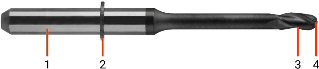
- Shank
- Tool ring
- Cutting edge
- Tool tip
Basic tool information
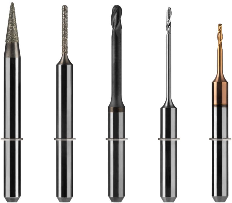
The different vhf tools offer different features that determine their behavior in different materials and applications. Therefore tools should only be used for the materials to which they are assigned via DENTALCAM. There are four main features that differentiate the milling tools:
- Number of teeth
- Tool length
- Coating
- Geometry of the cutting edge
Number of teeth
There are single-tooth and multi-tooth cutters.
- Single tooth cutters have a wide flute for a good chip evacuation when machining soft materials and materials that tend to smear.
- Multi-tooth cutters have narrower flutes for machining hard materials that do not tend to smear. The wear is divided between the teeth, which makes these cutters more durable than single tooth cutters.
The most common tools used in vhf machines are two tooth cutters.
Length of tool
The tool length of vhf tools differs depending on the number of axes of the milling machine.
- 4-axis machines use tools with 35 respectively 32 mm length. The tools for non-precious metals are 32 mm in length.
- 5-axis machines use tools with 40 respectively 35 mm length. The tools for non-precious metals are 35 mm in length.
Coating
The tools are coated to make them harder than the usual hard metal tools. There are different types of coating, the most common is the diamond coating.
- Due to their hardness, coated tools have a longer tool life. In addition, tool wear is significantly reduced and built-up edges are prevented.
- Tools for glass ceramics have a diamond grit, no diamond coating.
In the K1–K4, the tool needs to establish an electrical contact with the measuring plate. Therefore you cannot use diamond coated tools in the K1–K4.
Geometry of the cutting edge
There are three different geometries of the cutting edge for milling tools:
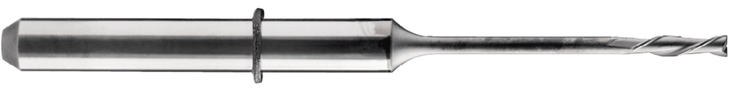
Radius cutter
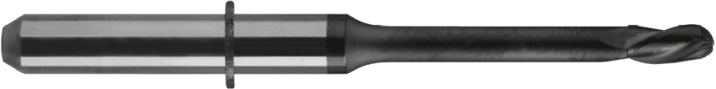
Radius cutter
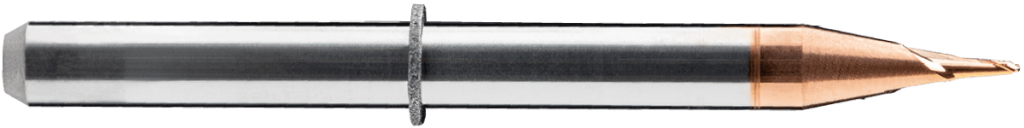
Special case: Conical radius cutter
- Radius cutters are milling tools with a rounded tool tip for machining 3D objects.
- Used for roughing, fine grinding or carving out fissures.
- Special case: If the tool tip is too small, the milling tool is not cylindrical but conical. This design ensures the needed stability of the tool.
Flat cutter
Flat cutter
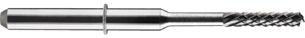
Special case: Flat cutter for fiber composites
- Flat cutters are milling tools with a flat tool tip for machining 90° angles.
- Flat cutters are used for the milling of connection geometries.
- Used for smoothing of edges as well as roughing PMMA and wax.
- Special case: Flat cutter with diamond teeth for machining fiber composites.
Torus cutters
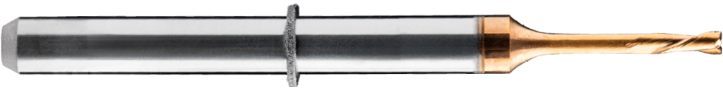
Torus cutters
- Torus cutters are milling tools with radii on the edges of the tool tip for better wear resistance. The center of the tool tip is flat.
- Torus grinding tools are used for the milling of connection geometries.
Even though grinding tools do not have a cutting edge, the tool tips of the grinding tools can differ. There are two different geometries of the cutting edge for grinding tools:
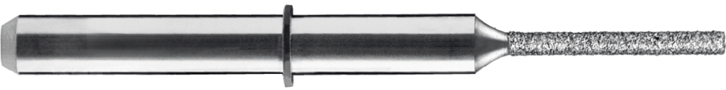
Radius grinding tools
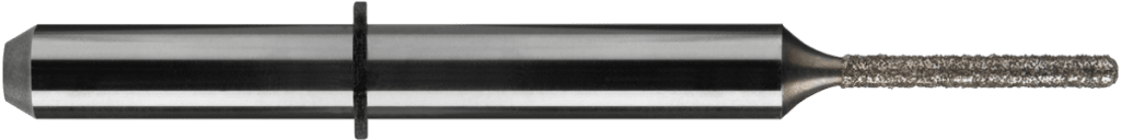
Radius grinding tool
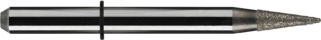
Special case: Conical radius grinding tool
- Radius grinding tools are tools with a rounded tool tip for machining 3D objects.
- Used for roughing, fine grinding or carving out fissures.
- Special case: If the tool tip is too small, the grinding tool is not cylindrical but conical. This design ensures the needed stability of the tool.
Torus grinding tools
Torus grinding tool
- Torus grinding tools are tools with radii on the edges of the tool tip for better wear resistance. The center of the tool tip is flat.
- Torus grinding tools are used for the milling of connection geometries.
Tool match codes
Match code
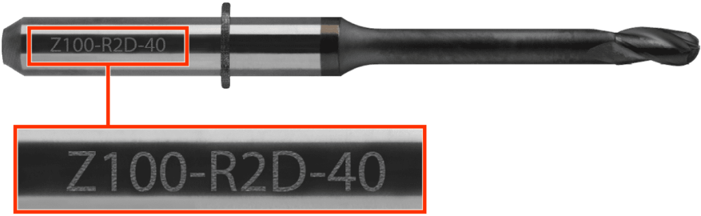
On every tool, a specific combination of letters and numbers is lasered. This combination of letters and numbers is called tool match code. Each tool can be identified by its specific match code. The codes differ for different materials to be processed, tool lengths and coating.
Structure for milling tools
All tool match codes are structured as follows:
Material to be processed Cutting edge diameter – Geometry of the cutting edge No. of teeth Coating – Tool length
The geometry of the cutting edge can be Radius, Flat or Torus.
Special case: The C200-FXD-38 has an X instead of the number of teeth to indicate the diamond teeth.
Example: Z100–R2D–40
Z – Zirconia
100 – 1.00 mm cutting edge diameter
R – Radius geometry of the cutting edge
2 – 2 teeth
D – Diamond coating
40 – 40 mm total length
Structure for grinding tools
All tool match codes are structured as follows:
Material to be processed Tool tip diameter – Tool tip geometry – Tool length
The tool tip geometry can be Radius or Torus.
Example: G100–R–35
G – Glass ceramics
100 – 1.00 mm tool tip diameter
R – Radius tool tip geometry
35 – 35 mm total length